
Phase 2: Cisco VXLAN EVPN in Practice - L2VNI, L3VNI, and External Connectivity
Building and verifying a VXLAN EVPN fabric by hand - L2VNI bridging, symmetric IRB L3VNI routing, VRF isolation, and eBGP-based external connectivity - before automating any of it with MCP.
Phase 1 got the topology up: 2 spines, 4 leafs, an external router, an OSPF underlay, and BGP - including the L2VPN EVPN address-family between leafs and spines. What wasn’t there yet was the actual VXLAN overlay: no nve1 interface, no VNI mapped to a VLAN or a VRF.
This lab builds that overlay by hand, on a topology specifically designed to force the distinction between three things that look similar from a ping test but aren’t:
- L2VNI - bridging the same VLAN across leafs
- L3VNI - routing between VLANs/subnets across leafs, using symmetric IRB
- Local IRB - routing between VLANs on the same leaf, which needs no VXLAN at all
Plus two things that go beyond a single VRF:
- VRF isolation - confirming two tenants don’t leak into each other
- External connectivity - getting a router outside the fabric to reach into a VRF, over genuine eBGP
Once this is built and verified manually, Phase 3 picks up with an MCP server so an AI client can run the same show commands itself - and this lab’s verification becomes the baseline to check the AI’s answers against.
Topology
This is the Netlab topology map that we’ll be using throughout this series:
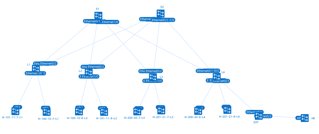
These are the devices in Netlab after boot-up:
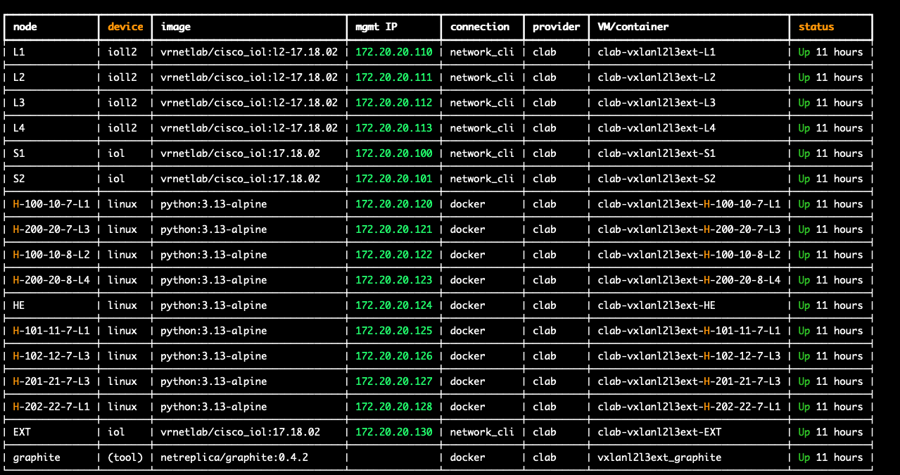
Click either image to open full size.
Nine hosts, two tenant VRFs, and an external router chain, deliberately spread across leafs so that every routing scenario actually has to prove itself:
| Host | VRF | VLAN | Subnet | Leaf |
|---|---|---|---|---|
| H-100-10-7-L1 | customer-a | 100 | 172.16.10.0/24 | L1 |
| H-100-10-8-L2 | customer-a | 100 | 172.16.10.0/24 | L2 |
| H-101-11-7-L1 | customer-a | 101 | 172.16.11.0/24 | L1 |
| H-102-12-7-L3 | customer-a | 102 | 172.16.12.0/24 | L3 |
| H-200-20-7-L3 | customer-b | 200 | 172.16.20.0/24 | L3 |
| H-200-20-8-L4 | customer-b | 200 | 172.16.20.0/24 | L4 |
| H-201-21-7-L3 | customer-b | 201 | 172.16.21.0/24 | L3 |
| H-202-22-7-L1 | customer-b | 202 | 172.16.22.0/24 | L1 |
| EXT / HE | - | external | behind EXT router | - |
customer-a uses L3VNI 50001; customer-b uses L3VNI 60001.
Why three VLANs per VRF
The host naming (H-<vlan>-<subnet>-<host>-<leaf>) has a purpose during the lab. For customer-a:
H-100-10-7-L1↔H-100-10-8-L2- same VLAN, different leaf → this can only work via L2VNI.H-100-10-7-L1↔H-101-11-7-L1- different VLAN, same leaf (L1has both 100 and 101 locally) → this works via local IRB, no VXLAN involved at all, even though it crosses subnets.H-100-10-7-L1↔H-102-12-7-L3- different VLAN, different leaf, andL1has no VLAN 102 locally → this is the only scenario that actually forces traffic through symmetric IRB via the L3VNI.
customer-b mirrors this exactly (VLANs 200/201/202), with VLAN 202 deliberately placed on L1 - a leaf that carries no other customer-b VLAN - so that direction is forced through the L3VNI too. Without this design, it’s easy to configure something that looks like working L3VNI routing but is secretly just local IRB on one leaf the whole time.
L2VNI - Layer 2 VXLAN bridging
Config, per leaf, per VLAN - an EVPN instance plus the VLAN-to-VNI binding:
l2vpn evpn instance 100 vlan-based
 encapsulation vxlan
 route-target export 100:10100
 route-target import 100:10100
 no auto-route-target
vlan configuration 100
 member evpn-instance 100 vni 10100
interface nve1 maps the VNI to a multicast group for BUM traffic:
interface nve1
 member vni 10100 mcast-group 239.0.0.100
Ping (H-100-10-7-L1 → H-100-10-8-L2, 172.16.10.8):
64 bytes from 172.16.10.8: seq=0 ttl=64 time=1.778 ms
64 bytes from 172.16.10.8: seq=1 ttl=64 time=1.725 ms
--- 172.16.10.8 ping statistics ---
4 packets transmitted, 4 packets received, 0% packet loss
TTL stayed at 64 - confirms the packet was bridged, not routed. That number matters more here than it looks; it’s the main way to tell L2VNI and L3VNI apart from a ping alone, and it’s what makes the L3VNI test below meaningful instead of just “it pinged.”
BGP EVPN Type-2 route for the remote host, seen on L1:
show bgp l2vpn evpn
Route Distinguisher: 10.0.0.2:100
 *>i  [2][10.0.0.2:100][0][48][AAC1ABCF3C43][0][*]/20
                      10.0.0.2                 0    100      0 ?
10.0.0.2 is L2’s loopback/VTEP - the MAC was learned via EVPN from the remote leaf, not a local port.
MAC address table on L1:
show mac address-table vlan 100
Vlan    Mac Address       Type        Ports
----    -----------       --------    -----
 100    aac1.ab15.c28d    DYNAMIC     Et0/3
 100    aac1.abff.44c6    DYNAMIC     Et0/3
L3VNI - symmetric IRB routing
Per leaf, per VRF, this needs: a VRF definition with matching RD/route-target (“stitching”) on every leaf sharing that VRF, a dedicated L3VNI-anchor SVI, and an nve1 binding of the L3VNI to the VRF. From L1 (customer-a):
vrf definition customer-a
 rd 65000:1
 route-target export 65000:1
 route-target import 65000:1
 address-family ipv4
  route-target export 65000:1 stitching
  route-target import 65000:1 stitching
 exit-address-family

interface Vlan501
 description cust-a svi for l3vni
 vrf forwarding customer-a
 ip address 99.99.1.1 255.255.255.0
 no autostate

interface nve1
 member vni 50001 vrf customer-a

router bgp 65000
 address-family ipv4 vrf customer-a
  advertise l2vpn evpn
  redistribute connected
 exit-address-family
Two things tripped me up while building this, silently, and they’re worth remembering more than the config above:
advertise l2vpn evpndoesn’t turn on by itself. None of the other config - the VRF definition, the RD, the route-target, the L3VNI binding onnve1- triggers it. Without this command explicitly added underaddress-family ipv4 vrf customer-a, the VRF’s IPv4 routes stay local and never get redistributed into BGP L2VPN EVPN as Type-5 routes, no matter how correct everything else is. Remote leafs simply never learn them.- The L3VNI-anchor SVI needs
no autostate.Vlan501has no physical ports - it only exists to anchor the L3VNI to the VRF - so IOS-XE’s default autostate behavior keeps it down, which silently breaks the L3VNI path even with otherwise-correct BGP config.
Reachability matrix
| Source | Destination | Mechanism | Why | Result |
|---|---|---|---|---|
| H-100-10-7-L1 | H-100-10-8-L2 | L2VNI | same VLAN 100, different leaf | ✅ 0% loss |
| H-100-10-7-L1 | H-101-11-7-L1 | Local IRB (no VXLAN) | different VLAN, same leaf | ✅ 0% loss |
| H-100-10-7-L1 | H-102-12-7-L3 | L3VNI (symmetric IRB) | different VLAN + leaf; L1 has no VLAN 102 locally |
✅ 0% loss |
| H-200-20-7-L3 | H-200-20-8-L4 | L2VNI | same VLAN 200, different leaf | ✅ 0% loss |
| H-200-20-7-L3 | H-201-21-7-L3 | Local IRB (no VXLAN) | different VLAN, same leaf | ✅ 0% loss |
| H-200-20-7-L3 | H-202-22-7-L1 | L3VNI (symmetric IRB) | different VLAN + leaf; L3 has no VLAN 202 locally |
✅ 0% loss |
any customer-a host |
any customer-b host |
VRF isolation | no route leaking configured | ❌ 100% loss (expected) |
The remaining leaf-pair combinations (L2↔L1’s VLAN 101, L4↔L3’s VLAN 201, etc.) were tested too - I just haven’t included every individual result here, since they follow the identical L3VNI mechanism as the rows shown above.
Ping (H-100-10-7-L1 → H-102-12-7-L3, 172.16.12.7 - the true cross-leaf L3VNI case):
64 bytes from 172.16.12.7: seq=0 ttl=63 time=1.833 ms
64 bytes from 172.16.12.7: seq=1 ttl=63 time=2.071 ms
--- 172.16.12.7 ping statistics ---
4 packets transmitted, 4 packets received, 0% packet loss
TTL dropped to 63 this time - actually routed, not bridged, unlike the L2VNI ping above. Same 0% loss, different mechanism entirely - this is exactly the distinction the topology was designed to expose.
BGP EVPN Type-5 route on L1, learned from L3:
show bgp l2vpn evpn route-type 5
BGP routing table entry for [5][65000:1][0][24][172.16.12.0]/17, version 96
Paths: (2 available, best #2, table EVPN-BGP-Table)
  Refresh Epoch 5
  Local
    10.0.0.3 (metric 21) (via default) from 10.0.0.5 (10.0.0.5)
      Origin IGP, metric 0, localpref 100, valid, internal, best
      EVPN ESI: 00000000000000000000, Gateway Address: 0.0.0.0, VNI Label 50001, MPLS VPN Label 0
      Extended Community: RT:65000:1 ENCAP:8 Router MAC:AABB.CC80.0D00
      Originator: 10.0.0.3, Cluster list: 10.0.0.5
RIB entry on L1:
show ip route vrf customer-a 172.16.12.0
Routing entry for 172.16.12.0/24
  Known via "bgp 65000", distance 200, metric 0, type internal
  Last update from 10.0.0.3 on Vlan501, ... ago
  * 10.0.0.3 (default), from 10.0.0.5, ... via Vlan501
The route rides Vlan501 - the L3VNI-anchor SVI, not Vlan100. That’s symmetric IRB end to end: routed in via the anchor SVI on the ingress leaf, carried across the fabric in the L3VNI, routed back out via the destination leaf’s own anchor SVI.
VRF isolation
customer-a and customer-b are not leaked into each other. Confirmed with H-100-10-7-L1 → H-200-20-7-L3 (172.16.20.7):
PING 172.16.20.7 (172.16.20.7): 56 data bytes
--- 172.16.20.7 ping statistics ---
3 packets transmitted, 0 packets received, 100% packet loss
Route-target leaking between VRFs is possible (import each other’s route-target under the VRF’s BGP address-family) but was deliberately left out here; nothing in this lab needed customer-a and customer-b to talk to each other.
External connectivity
Built and working for customer-b. customer-a isn’t configured yet - same recipe applies, see the note at the end.
Design. The L4↔EXT link is a member interface of customer-b’s VRF on both ends: L4 has it in customer-b like any other VRF interface, and EXT - normally just a plain external router - was given a matching local vrf definition customer-b too, with both its interfaces (L4-facing and HE-facing) inside it. L4 and EXT then peer over genuine eBGP (L4 in AS 65000, EXT in AS 65500) inside that VRF, so routes flow dynamically in both directions instead of via static leaking:
customer-b (L3VNI 60001)
      |
     L4  ---- eBGP (AS 65000 <-> AS 65500), vrf customer-b ----  EXT  ----  HE
Config - L4:
interface Ethernet0/3
 description L4 -> EXT
 vrf forwarding customer-b
 ip address 10.255.0.1 255.255.255.252

router bgp 65000
 address-family ipv4 vrf customer-b
  advertise l2vpn evpn
  redistribute connected
  neighbor EXTERNAL peer-group
  neighbor EXTERNAL remote-as 65500
  neighbor EXTERNAL send-community both
  neighbor 10.255.0.2 peer-group EXTERNAL
  neighbor 10.255.0.2 activate
 exit-address-family
Config - EXT:
vrf definition customer-b
 rd 65000:2
 address-family ipv4
 exit-address-family

interface Ethernet0/1
 description EXT -> L4
 vrf forwarding customer-b
 ip address 10.255.0.2 255.255.255.252

interface Ethernet0/2
 description EXT -> HE
 vrf forwarding customer-b
 ip address 172.16.0.16 255.255.255.0

router bgp 65500
 address-family ipv4 vrf customer-b
  network 172.16.0.0 mask 255.255.255.0
  neighbor EXTERNAL peer-group
  neighbor EXTERNAL remote-as 65000
  neighbor EXTERNAL send-community both
  neighbor 10.255.0.1 peer-group EXTERNAL
  neighbor 10.255.0.1 activate
 exit-address-family
Ping - HE → customer-b host directly on L4 (172.16.20.8):
64 bytes from 172.16.20.8: seq=0 ttl=63 time=2.132 ms
64 bytes from 172.16.20.8: seq=3 ttl=63 time=8.187 ms
--- 172.16.20.8 ping statistics ---
4 packets transmitted, 4 packets received, 0% packet loss
Ping - HE → customer-b host across the fabric, via the true L3VNI to L1 (172.16.22.7):
64 bytes from 172.16.22.7: seq=0 ttl=62 time=1.927 ms
64 bytes from 172.16.22.7: seq=3 ttl=62 time=1.879 ms
--- 172.16.22.7 ping statistics ---
4 packets transmitted, 4 packets received, 0% packet loss
TTL of 62 here, not 63 - one extra hop compared to reaching L4 directly, consistent with the packet also crossing the L3VNI from L4’s VRF over to L1 to reach H-202-22-7-L1. An external client reaching a host that itself required symmetric IRB to reach from inside the fabric - both mechanisms stacked, and the TTL count confirms it rather than just asserting it.
Ping - the reverse direction, a customer-b host → HE (H-200-20-7-L3 → 172.16.0.11):
64 bytes from 172.16.0.11: seq=0 ttl=62 time=2.297 ms
64 bytes from 172.16.0.11: seq=1 ttl=62 time=2.005 ms
64 bytes from 172.16.0.11: seq=2 ttl=62 time=1.782 ms
--- 172.16.0.11 ping statistics ---
3 packets transmitted, 3 packets received, 0% packet loss
So actual host-to-host traffic works cleanly in both directions - this isn’t a one-way tunnel.
customer-a: not built yet. Same recipe applies - give EXT a third interface (or sub-interface) into customer-a’s VRF, add a matching vrf definition customer-a on EXT, and set up a second eBGP session in that VRF between EXT and whichever leaf carries it.
What’s next?
L2VNI, L3VNI (with the local-IRB and true-symmetric-IRB distinction actually proven, not assumed), VRF isolation, and external connectivity - all built and verified by hand. I know what “correct” looks like on this fabric.
Phase 3 is where MCP comes in: a server built on Netmiko so an AI client can run show commands against these same leafs and spines. The verification in this lab becomes the baseline I’ll compare the AI’s output against - starting with something as simple as “does the AI also notice the TTL difference between the L2VNI and L3VNI pings, or does it just report 0% packet loss and call it done.”
Code
The configuration and verification notes for this lab are in:
net-auto-labs/vxlan_l2_l3_external